Table of contents
Pick & Place Cell
Description
The Pick & Place Cell is an automated manufacturing system designed to execute handling, sorting, and transfer operations in a discrete production environment. The cell’s behavior is governed by event-driven logic where sensors and digital actuators interact to determine the system’s response to operating conditions. Communication within the system can be managed through industrial protocols like Modbus TCP/IP or MQTT.
The virtual pick&place cell consists of several assets (see Figure 1-Figure 9):
-
Cartesian Robot: A programmable robotic arm is primarily aimed at picking individual items from Conveyor 2 and place them into boxes on Conveyor 1 (Figure 1).
-
Objects: The system manipulates two types of objects, i.e. items (Simple-shaped parts that are picked from Conveyor 2 and placed into boxes) and boxes (containers that move along Conveyor 1 to be filled with items by the robot). See Figures 2 and 3.
-
Control Panel: the main user interface (Figure 4). It is equipped with four physical buttons (Start, Stop, Initialization, Emergency) and a three-position State Selector for choosing the operational mode. A potentiometer is also included to select the number of items to be placed in each box.
-
Conveyors: The scene includes two main conveyor belts, Conveyor 1 and Conveyor 2. Conveyor 1 carries boxes to be filled, while Conveyor 2 transports the items that will be picked up. (Figure 5)
-
Unloading Slides: Located at the end of each conveyor, these slides enable the physical evacuation of materials once processing is complete. (Figure 6)
-
Signal Pole: A vertical pole with three lights (red, yellow, green) provides visual feedback on the system’s operational status. (Figure 7)
-
Protective Grids: The cell also includes solid grids to protect critical areas and perforated grids that support functional elements like the Control Panel. (Figure 8)
-
Detection Barriers: Both conveyors are equipped with sensor-receiver pairs that detect the presence, passage, and correct positioning of objects. (Figure 9)
Digital Model
The scene configuration and the 3D models (Fugures 1-9) of the use case are available online. The use case can be visualized using VEB.js tool (see Figures 10 and 11).
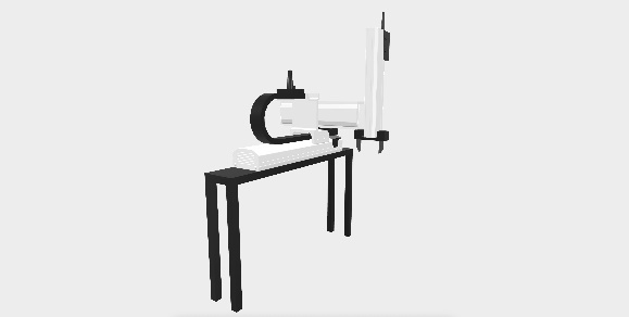
Figure 1: Cartesian robotic arm used for pick and place operations.
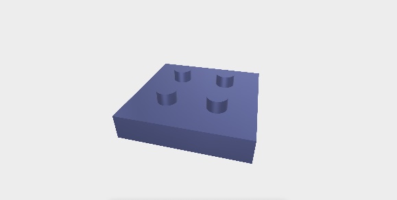
Figure 2: Basic item shape manipulated by the robot.

Figure 3: Transport box used for item collection.
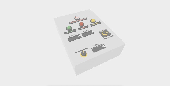
Figure 4: Control Panel with physical interface (buttons, selectors)
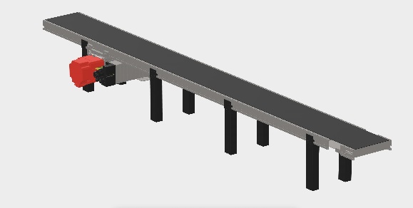
Figure 5: Conveyor belt with motor for item transport
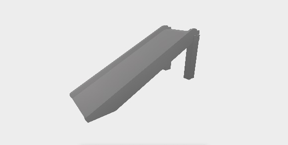
Figure 6: Slide used for unloading processed items

Figure 7: Signal pole indicating system state.
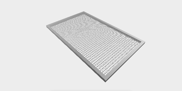
Figure 8: Perforated protective grid supporting the Control Panel
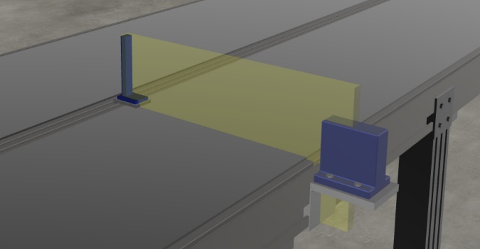
Figure 9: Barrier sensors for object detection on conveyors
The whole cell and each of its assets are shown in Figure 10 and Figure 11.
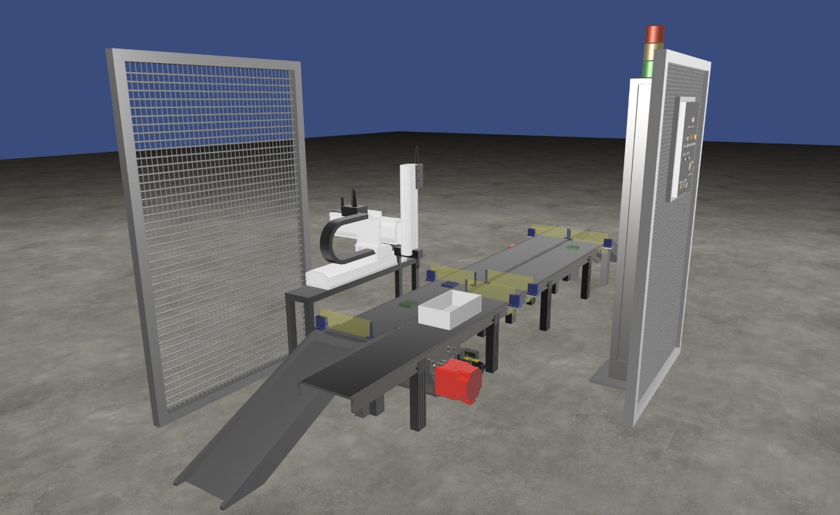
Figure 10: Full view of the Pick&Place cell.
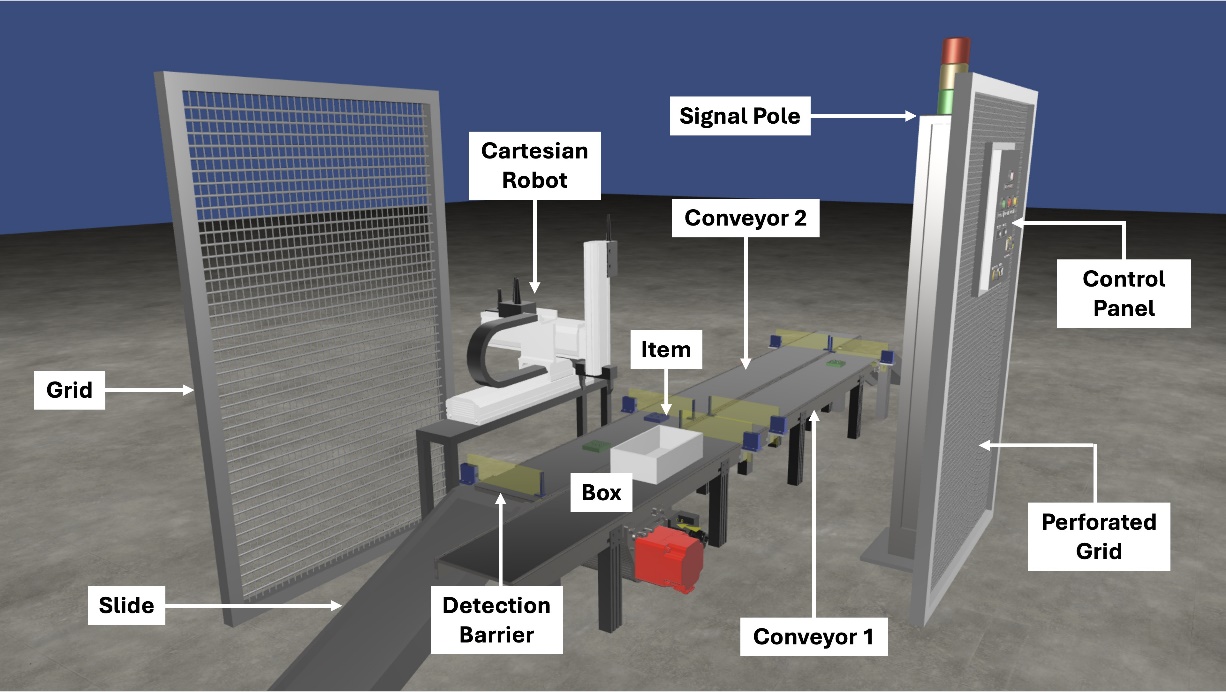
Figure 11: Full view of the Pick&Place cell, including labels of each asset.