Table of contents
Robotic Motion Planning
This workflows is related to robotic motion planning, addressing the assessment and generation phases by developing and updating the digital twin of a robotics lab. Therefore, special attention is paid to the technical steps ranging from the creation of a 3D scene to the simulation of robot trajectories.
1. Learning Objectives
The learning objectives covers knowledge types A, B, and C (see Sect.3.1). Table 6 reports the ILOs and the associated knowledge type.
| ILO ID | Knowledge type | Description |
|---|---|---|
| I1 | A | Identify assets in a robotics lab. |
| I2 | B | Classify the outcome of a robot trajectory in a 3D space. |
| I3 | C | Analyze and elaborate messages of a robot controller. |
| I4 | C | Visualize a robot trajectory in a virtual environment. |
| I5 | C | Receive and elaborate messages via standard communication protocol. |
| I6 | C | Generate a new robot trajectory. |
Table 6: ILOs and knowledge type
2. Use Case
The learning workflow was applied to the PERFORM Lab (Personal Robotics for Manufacturing Laboratory) at CNR-STIIMA (Figure 8).
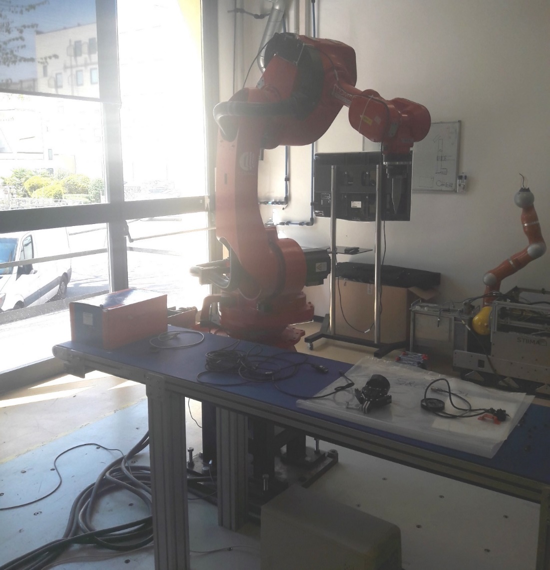
Figure 8: PERFORM Lab
3. Learning Activities
The learning activities are organized into three levels of increasing difficulty: 1) Visualization and assessment of robot trajectories; 2) Receive and elaborate messages from a robot controller; 3) Generate and assess new robot trajectories.
Each level consists of tasks associated with specifics ILOs as reported in Table 7.
| Task ID | Task name | Task description | ILO |
|---|---|---|---|
| T1.1 | Visualize the scene of the lab in a VR environment. | Using a VR tool (e.g. VEB.js), visualize the scene configuration of the lab in a VR environment and zoom-in to identify specific assets (i.e. robot tool, conveypr, workpiece) by highlighting their local origin. | I1 |
| T1.2 | Elaborate trajectories and generate an animation | Elaborate the 4 trajectories (joint positions) and generate an animation that can be played in the selected VR environment. | I3 |
| T1.3 | Visualize robot trajectories | Visualize the robot trajectories in the selected VR environment. | I4 |
| T1.4 | Assess the execution of the trajectories | Assess the execution of the trajectories in terms of distance from the target and possible collisions. | I2 |
| T2.1 | Retrieve a trajectory via MQTT | Receive and save themessages containing the joint positions, as generated by an emulator of the robot controller. | I5 |
| T2.2 | Elaborate trajectories and generate an animation | Elaborate the trajectory (joint positions) and generate an animation that can be played in the selected VR environment. | I3 |
| T2.3 | Visualize robot trajectory | Visualize the robot trajectory in the selected VR environment. | I4 |
| T2.4 | Assess the execution of the trajectories | Assess the execution of the trajectory in terms of distance from the target and possible collisions. | I2 |
| T2.5 | Develop an MQTT client | Develop an MQTT client that is able to 1) receive the messages sent by the robot emulator (using OntoGuiWeb), 2) elaborate the content of the message an animation, 3) publish the animation via MQTT. | I5 |
| T3.1 | Generate a new trajectory | Generate a trajectory for the robot using any support method/tool, given the starting and target positions. | I6 |
| T3.2 | Elaborate the trajectory | Elaborate the trajectory (joint positions) and generate an animation that can be played in the selected VR environment. | I3 |
| T3.3 | Visualize robot trajectory | Visualize the robot trajectory in the selected VR environment. | I4 |
| T3.4 | Assess the execution of the trajectories | Assess the execution of the trajectory in terms of distance from the target and possible collisions. | I2 |
Table 7: Learning tasks and ILOs
4. Technology
Assets and scene configuration
A digital twin of the lab has been developed to support research and teaching activities. Digital resources are available online, including the 3D models of the assets in gLFT format and the scene configuration defined in a JSON file according to a specific schema.
Visualization in VR environment
The 3D scene can be visualized using several VR tools/environments, such as Unity, UnrealEngine, Godot, BabylonJS, etc.
Herein, VEB.js prototype tool is employed, taking advantage of its reconfigurable model-driven approach. Any browser can be used to visualize the PERFORM Lab with VEB.js.
Simulation
The planning, management, and monitoring of robots are a complex task that can be supported by specific software tools, e.g. Gazebo, RoboDK, Process Simulate, and ROS-based tools like MoveIt.
The attention is focused on the simulation of robot trajectories. However, the actual generation of these trajectories is out of scope as they are taken as input. Specifically, robot trajectories for the PERFORM Lab were generating using ROS-MoveIt.
During the execution of the trajectory, the robot controller can communicate the joint state (i.e. position, velocity, force/torque, etc.) that in turn can be stored (e.g. in a text-based file) or published (e.g. via MQTT). Herein, we take in consideration only the joint position, i.e. the rotation angle of the joint. The joint angles are likely to be measured by sensors or encoders that are attached to the robot joints. These sensors can generate data at a high rate, potentially several times per second or even faster, depending on the specific application and the performance requirements.
The joint positions of the robot in the PERFORM Lab are saved at 10 Hz (i.e. one position is stored every 0.1 [s]) in a JSON file that contains a list of position items, where each item defines the angles of the joints in radians [rad]. Here below an example of item is shown:
{
“J1”: 0.0,
“J2”: 0.0,
“J3”: 1.57,
“J4”: 0.0,
“J5”: -1.57,
“J6”: 0.0,
“J7”: 0.0,
“J8”: 0.0,
“J9”: 0.0,
“J10”: 0.0
}
Each item of the list reports by default the value of 10 joint angles. Robot_1 of PERFORM Lab consists of 6 joints, therefore only joints from “J1” to “J6” contain relevant values while the others (from “J7” to “J10”) will be always set to zero.
An example can be seen in the file that defines a trajectory moving the tool along the vertical axis.
MQTT Communication
MQTT (Message Queuing Telemetry Transport) is a lightweight, publish-subscribe messaging protocol that is commonly used in the Internet of Things (IoT) and other applications.
MQTT can be exploited for bi-directional communications with robots:
-
sending feedback about joint states
-
receiving commands for the execution of trajectories
Different programming languages can be used to develop MQTT clients, e.g. JavaScript and Pyhton libraries. In addition to publishers and subscribers, the MQTT architecture needs a broker to manage messages.
Several resources are freely available online to develop MQTT architectures, such as free public MQTT broker (e.g. broker.emqx.io) and libraries to develop MQTT components (e.g. MQTT.js).
The robot controller can publish a message containing the current joint states. Because of security resons, the messages can be generated by an emulator of the robot controller that is launched using the web application OntoGuiWeb. Specifically, the module MQTT Sync provides functionalities as an MQTT client to publish messages and subscribe to topics.
VEB.js can play the role of both publisher and subscriber, exchanging messages that are structured to the animation json schema.
5. User Experience
The assessment of the learning task is carried out by analyzing the output of the various tasks, as defined in Table 8. The following trajectories are provided as list of joint positions defined in a JSON file:
| Task ID | Task | Output |
|---|---|---|
| T1.1 | Visualize the scene of the lab in a VR environment. | Screenshots of the VR scene |
| T1.2 | Elaborate trajectories and generate an animation | 1) Animation files of the 4 trajectories; 2) Script/program to elaborate the trajectories. |
| T1.3 | Visualize robot trajectories | Video of the 4 trajectories in the selected VR environment. |
| T1.4 | Assess the execution of the trajectories | 1) Does the trajectory reach the goal (yes/no)?; 2) Identification of possible collisions of the robot or tool with other assets; 3) Distance of the tip of the Tool from the local origin of Workpiece |
| T2.1 | Retrieve a trajectory via MQTT | Trajectory of the robot in a text-based format |
| T2.2 | Elaborate trajectories and generate an animation | Animation file of the trajectory for the VR environment to play the animation. |
| T2.3 | Visualize robot trajectory | Video of the trajectory in the selected VR environment. |
| T2.4 | Assess the execution of the trajectories | 1) Does the trajectory reach the goal (yes/no)?; 2) Identification of possible collisions of the robot or tool with other assets; 3) Distance of the tip of the Tool from the local origin of Workpiece |
| T2.5 | Develop an MQTT client | Program/script implementing the MQTT client |
| T3.1 | Generate a new trajectory | 1) Description of the workflow to generate the trajectory; 2) Trajectory of the robot in a text-based format |
| T3.2 | Elaborate the trajectory | Animation file of the trajectory for the VR environment to play the animation. |
| T3.3 | Visualize robot trajectory | Video of the trajectory in the selected VR environment. |
| T3.4 | Assess the execution of the trajectories | 1) Does the trajectory reach the goal (yes/no)?; 2) Identification of possible collisions of the robot or tool with other assets; 3) Distance of the tip of the Tool from the local origin of Workpiece |
Table 8: Expected outcome of the learning tasks