Table of contents
Step Motor
Description
Step motor (Figure 1), adopted as a use case for Workflows W04 and W08, consists of Rotor, Stator, Front Bearing, Rear Bearing, Front Endcap, Rear Endcap and four M3 Screws.
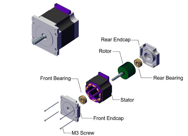
Figure 1: Step motor
In Workflow W04 the motor is reduced to 6 parts/subassemblies denoted by letters A-E in Figure 2. It is assumed that rotor and stator are introduced into assembly process as subassemblies. Furthermore, since it is evident that the last operation in assembly process should be fixing the assembly using four screws, these parts are not considered during assembly sequence analysis.
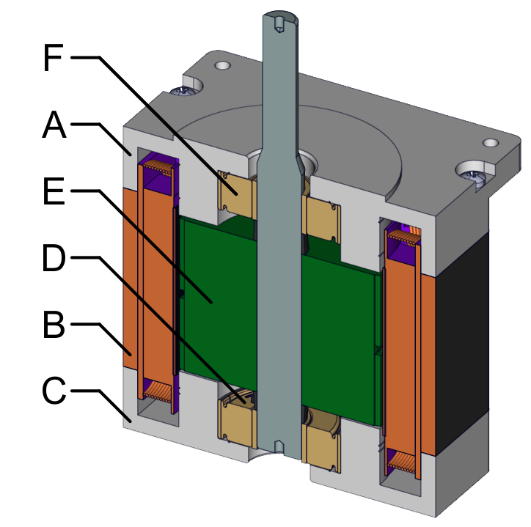
Figure 2: Step motor parts and sub-assemblies considered in Workflow W04