Table of contents
Assembly Line
Description
This use case consists in an assembly line that produces self-closing concealed cabinet hinges. The assembly line includes 19 workstations, each performing specific tasks (e.g., pick and place, screw tightening, riveting) to assemble the components of the self-closing concealed cabinet hinge. These components are shown in Figure 1 and listed in Table 1. The sequence of operations is detailed in Table 2, indicating the input components and the workstation responsible for each operation. Work-in-progress hinges are moved along the line on a pallet.
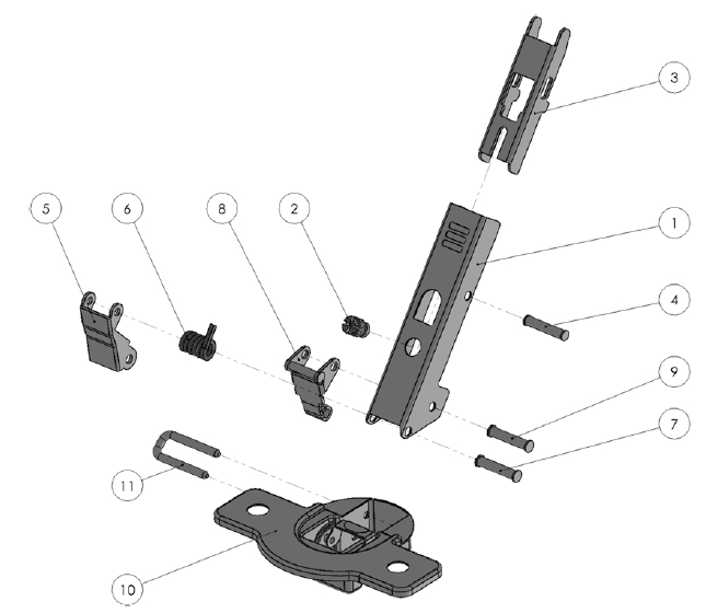
Figure 1: Hinge components
| Component ID | Label |
|---|---|
| Wing | 1 |
| WingScrew | 2 |
| Clip | 3 |
| Pin1-1 | 4 |
| Connector1 | 5 |
| Spring | 6 |
| Pin1-2 | 7 |
| Connector2 | 8 |
| Pin1-3 | 9 |
| Box | 10 |
| Hook | 11 |
Table 1: Hinge components with label
| Operation ID | Operation type | Input Component | Station ID | Description |
|---|---|---|---|---|
| 1 | pick&place | Wing | PPW1 | Wing is picked from the upstream buffer and placed on the rotating table. |
| 2 | tightening | WingScrew | T1 | WingScrew is aligned to the corresponding hole on the Wing and screwed. |
| 3 | pick&place | PPH1 | The wip hinge is taken from the rotating table and placed on a conveyor. | |
| 4 | pick&place | RPP1 | A robot of workstation RPP1 picks the wip hinge from a conveyor and places it on a pallet. | |
| 5 | pick&place | Clip | PP1 | Clip is assembled on Wing, hooking to the WingScrew. |
| 6 | pin insertion | Pin1-1 | PI1 | Pin1-1 is inserted to fix Clip on Wing. |
| 7 | riveting | R1 | Pin1-1 is riveted. | |
| 8 | pick&place | Connector1 | PP2 | Connector1 is assembled on Wing. |
| 9 | pick&place | Spring | PP3 | Spring is assembled on Wing. |
| 10 | pin insertion | Pin1-2 | PI2 | Pin1-2 is inserted to fix Connector1 and Spring on Wing. |
| 11 | riveting | R2 | Pin1-2 is riveted. | |
| 12 | pick&place | Connector2 | PP4 | Connector2 is assembled on Wing. |
| 13 | pin insertion | Pin1-3 | PI3 | Pin1-3 is inserted to fix Connector2 on Wing. |
| 14 | riveting | R3 | Pin1-3 is riveted. | |
| 15 | pick&place | Box | PP5 | Box is assembled on Wing. |
| 16 | pin insertion | Hook | PI4 | Hook is inserted to fix Box on Wing. |
| 17 | riveting | R4 | Hook is riveted. | |
| 18 | inspection | C1 | The finished hinge is visually inspected by a camera. | |
| 19 | pick&place | CB1 | The finished hinge is picked from the pallet and placed in a box. |
Table 2: Operations and workstations
More details about the use case can be found here.
Digital Model
The scene configuration and the 3D models (Figures 2-8) of the use case are available online. The assembly line can be visualized using VEB.js tool (Figures 9 and 10).
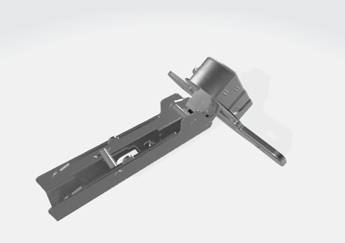
Figure 2: Hinge.
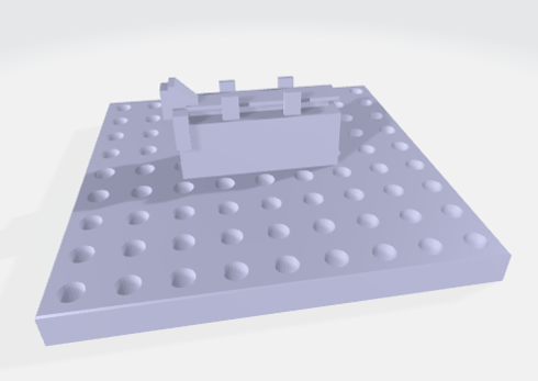
Figure 3: Pallet.
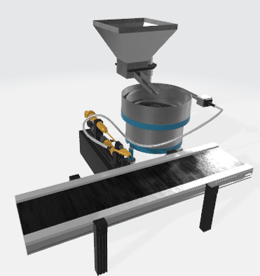
Figure 4: Pin insertion station.
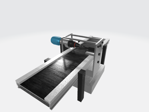
Figure 5: Riveting station.
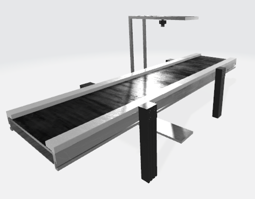
Figure 6: Inspection camera station
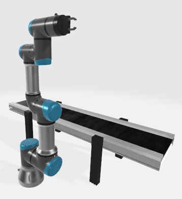
Figure 7: UR pick and place station
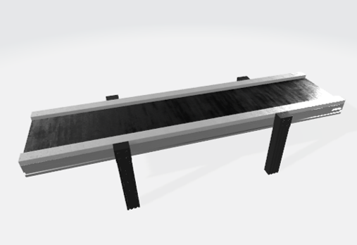
Figure 8: Conveyor
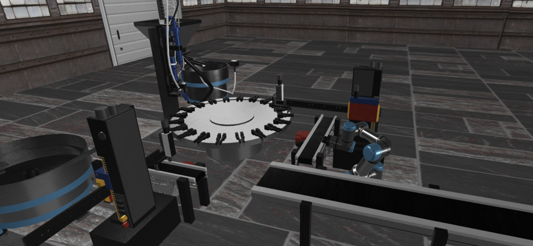
Figure 9: Assembly line (upstream part)
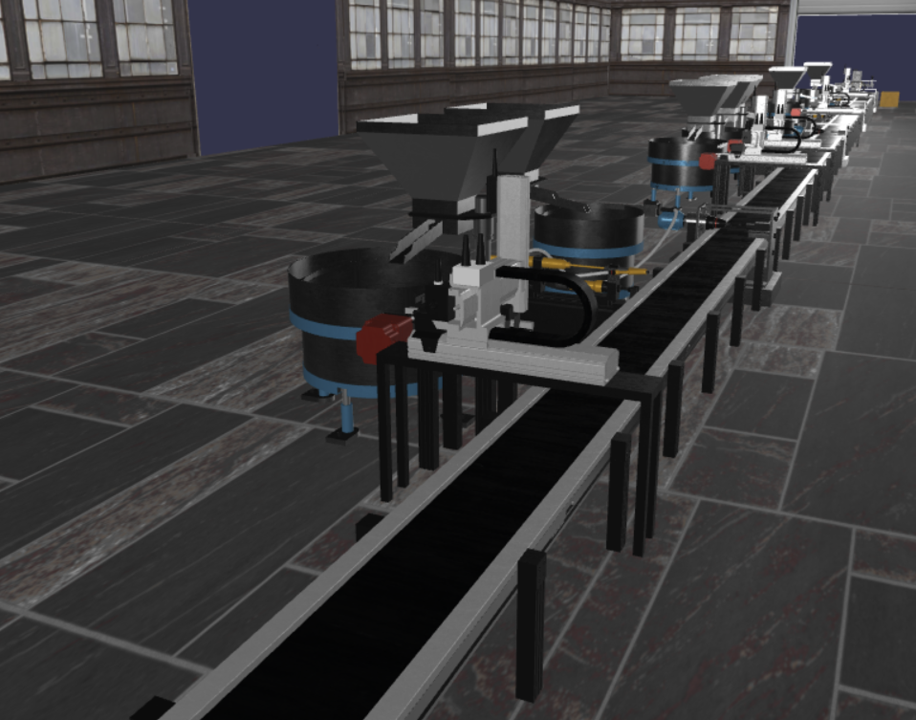
Figure 10: Assembly line (downstream part)