Table of contents
Assembly Sequence Analysis
Assembly sequence analysis represents a starting point in the design of assembly process and corresponding assembly system. In general, one product can be assembled in several ways using different sequences. When assembly process is intended to produce a large number of product instances, the technique of choice for its design is to find all feasible assembly sequences and to choose the most suitable sequence among them, using engineering rationale. For generation of all feasible assembly sequences there exist two widespread techniques – Cutset method [1, 3, 5] and Bourjault method [1, 2, 4, 5]. Both methods start from the Liaison Diagram that represents the liaisons (contacts, i.e., mates or joints) between parts in product assembly in the form of graph. In Liaison Diagram parts are represented by nodes and liaisons by links [1, 5]. The output of methods are precedence relations, i.e., the relations that define which subassemblies should precede the remaining subassemblies. These relations are obtained through addressing precedence questions that are set using certain rules that depend on the chosen method (Cutset or Bourjault).
Asking and answering the precedence questions represent critical points in teaching and learning Cutset and Bourjault methods. Implementation of extended reality (XR) tools during this process can significantly improve student’s understanding. Consequently, this workflow contains an approach to mastering Cutset and Bourjault methods using XR tools. In the presented workflow students ask and answer precedence questions on examples of assemblies by trying to mate/join parts in XR. Two examples, one referring to a simple assembly that showcases simple learning product and the other referring to a real-world example of step motor, are used. Following the workflow, a kind of hands-on experience that does not require the existence of real-world products and significant manual effort during assembling/disassembling products can be provided to students.
1. Learning Objectives
The objectives of workflow are to develop in students the following knowledge:
-
Factual Knowledge
-
Knowledge about alternative approaches to assembly sequence design and their characteristics.
-
Definition of Liaison Diagram and rules for its generation (loop closure rule and rules that product must follow).
-
Definition of precedence questions for Cutset and Bourjault methods and precedence relations; rules for asking and answering questions (superset and subset rules).
-
Definition of Liaison Sequence Diagram and rules for its generation.
-
Guidelines for selection of the most suitable sequence.
-
-
Conceptual Knowledge
-
Relation between Liaison Diagram, precedence questions in Bourjault and Cutset method and product design.
-
Relation between answers to precedence questions and possibility of mating parts within product.
-
Influence of the assembly sequence on the assembly process characteristics.
-
-
Procedural Knowledge
-
Procedure for generation of Liaison Diagram.
-
Procedure for making subassemblies and asking precedence questions in Cutset method, as well as the procedure for asking precedence questions in Bourjault method.
-
Generation of precedence relations based on answers to precedence questions.
-
Generation of Liaison Sequence Diagrams.
-
Apply XR tools to interact with the product and assemble/disassemble its parts.
-
-
Metacognitive Knowledge
-
Problem solving in assembly sequence design using XR tools.
-
Self-evaluate the understanding of the methods for assembly sequence design and validate answers to the precedence questions through experiments in XR.
-
The listed knowledge is related to the specific Intended Learning Outcomes (ILOs) that are listed in Table 1.
| ILO | Knowledge Type | ILO Description |
|---|---|---|
| I1 | 1.1 | Capability to choose suitable technique for assembly sequence design |
| I2 | 1.2, 3.1 | Understanding the liaisons (mates and joints) between parts in the product |
| I3 | 1.3, 3.2 | Understanding physical constraints and relations between parts and subassemblies within product |
| I4 | 2.1 | Understanding the influence of product design on assembly process |
| I5 | 2.2, 3.3 | Capability to define precedence of assembly operations within the process |
| I6 | 1.4, 3.4 | Capability to define all feasible assembly sequences for the selected product |
| I7 | 1.5, 2.3 | Capability to choose the most suitable assembly sequence |
| I8 | 3.5, 4.1 | Capability to apply XR tools to interact with virtual products and to extract useful information from a product by exploring it in virtual environment |
| I9 | 4.2 | Capability to self-evaluate their own learning achievements |
Table 1: ILOs with associated knowledge
2. Use Cases
The workflow for the assembly sequence analysis contains two use cases through which students obtain knowledge and skills listed in Section 1. Use Case 1 refers to the simple product that contains only four parts (Figure 1.a), whereas Use Case 2 represents a real-world product, i.e. a step motor (Figure 1.b).
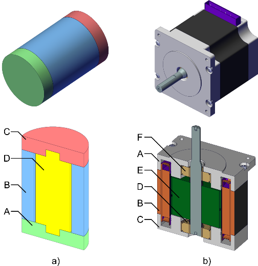
Figure 1: Products used in workflow: a) simple product (Use Case1), and b) step motor (Use Case 2)
3. Learning Activities
The workflow consists of eight learning tasks through which the students acquire intended knowledge and learning outcomes. The sequence of tasks along with their input and output are presented in Figure 2, whereas Table 2 contains the description of tasks and ILOs they contribute to. Tasks T2.0 to T8.0 are performed for both use cases – first for use case 1 where students get the first insight into the application of the methods, and after that for use case 2 where students get deeper understanding of the methods, assembly sequences and their relation to product design and assembly process. To make this document concise, Table 2 presents the application to use case 2, as more complex, in more details assuming that the implementation of tasks for use case 1 is simpler.
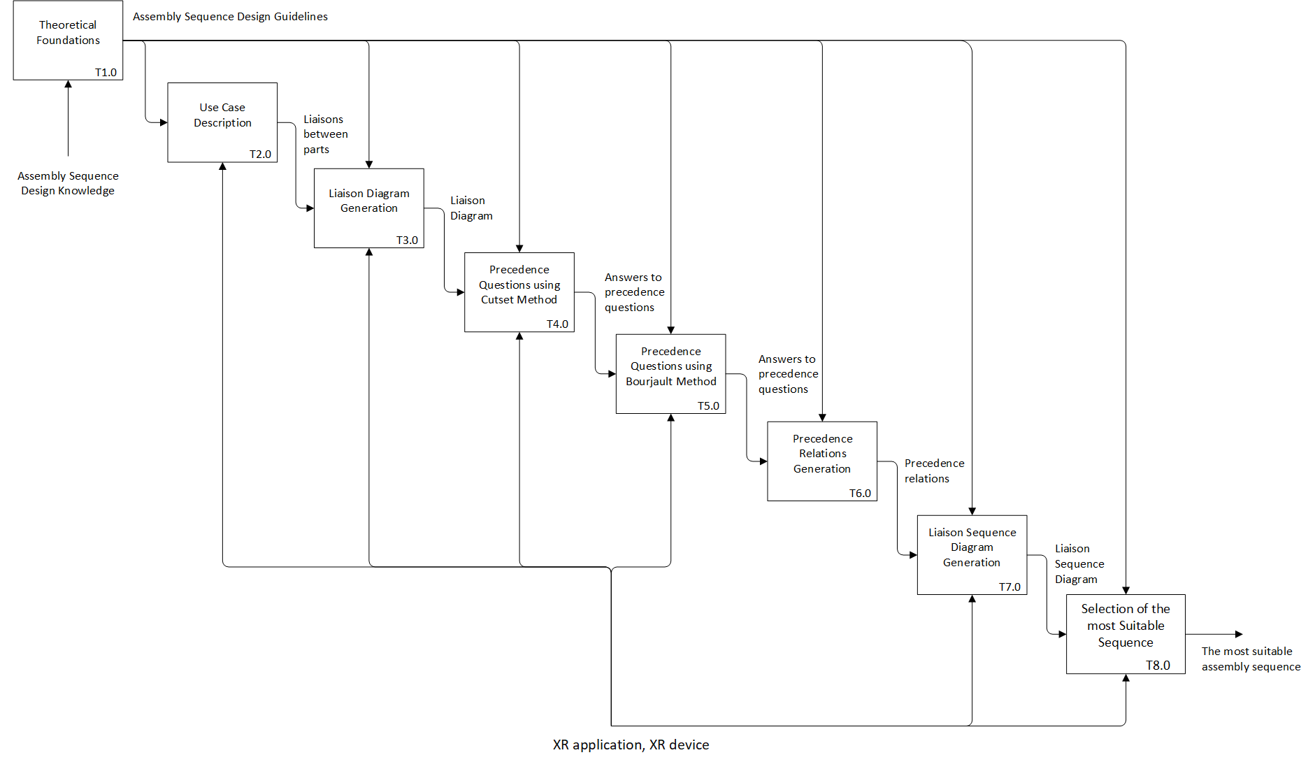
Figure 2: Learning Activities
| Task ID | Task Name | Task Description | ILO |
|---|---|---|---|
| T1.0 | Theoretical Foundations | Description: Students are introduced to the problem of assembly sequence analysis and design, as well as to the benefits and shortcomings of finding all feasible assembly sequences for the subsequent design of assembly system. The theoretical foundations, i.e., the principles and the methods for generation of all feasible sequences are presented to students, and in particular:
• Output: Assembly Sequence Design Guidelines | I1 I2 I5 I7 |
| T2.0 | Use Cases Description | Description: Students are introduced to the product that will be utilized as use case through its 3D exploded view and drawing. Use case 1:
Use case 2:
Furthermore, they immerse interactive virtual environment, explore the product and assemble/disassemble it in XR. Use case 1:
Use case 2:
Through virtual hands-on experience students get better insight into the product structure and types of joints and mates between parts. With the support of the exploded view and drawing of the product, as well as using experience from XR students detect the liaisons (mates and joints) between parts. This is the first task in which students enter XR and through this task they are also introduced to the basic principles of its functioning. • Output: Liaisons between parts | I2 I3 I8 |
| T3.0 | Liaison Diagram Generation | Description: Based on the experiments from T2.0, 3D exploded view, and drawing of product, as well as using list of parts and liaisons between them that is created in T2.0, students generate liaison diagram for the use case product. They enter XR environment and make the Liaison Diagram using available lines on the canvas.
They also have an opportunity to see the correct Liaison Diagram by clicking on “Show button”. In case they find any discrepancies between the Liaison Diagram they generated and the correct diagram, they can further explore the product and find the reason for the mistake they made.
• Output: Liaison Diagram • Resources: XR application, XR device | I2 I8 I9 |
| T4.0 | Precedence Questions using Cutset Method | Description: Students are immersed in XR application created for the selected use cases and ask and answer the precedence questions for Cutset method. Use case 1 has the following scene:
and the scene for use case 2 is as follows:
The procedure for asking and answering questions includes several steps. In the first step, students define subassemblies Si and Sj within the product following the prescribed rules:
Subassemblies are generated by selecting check boxes next to the parts that belong to them.
The liaisons that are disconnected by creating the subassemblies are automatically removed from liaison diagram to facilitate student’s decision if the subassemblies are created by the above-listed rules.
Simultaneously, the parts that belong to the subassembly Sj are marked red in product model.
If the subassemblies are created according to the above-listed rules, using XR model of the product, students try to disassemble subassembly Si from subassembly Sj and answer the question: Can subassembly Si be disassembled from subassembly Sj?
The answer to the question is entered into the selected fields in XR application.
If the answer to a question is NO, the procedure is repeated for the cut parts of diagram. After asking and answering precedence questions, the answers are stored in a txt file to be used in task T6.0. • Output: Answers to precedence questions | I3 I4 I8 |
| T5.0 | Precedence Questions using Bourjault Method | Description: Students are immersed in XR applications created for the selected use cases and, with the help of the developed applications, ask and answer the precedence questions for Bourjault method. Use case 1 has the following scene:
whereas the scene for use case 2 is as follows:
The left side of canvas contains explanation of possible answers to precedence questions and instructions on how to consider the parts whose liaisons are disconnected. In the central part is the field for selecting the liaisons considered in a question, as well as the liaison diagram that is automatically generated. Finally, the left side of canvas represents tables for asking and answering the precedence questions. In front of canvas there are two instances of assemblies on which students, based on the automatically created liaison diagram, turn on the subassemblies/parts which are assembled through establishing the liaison that is in the first part of the question (liaison i). Since the liaison diagrams in both use cases represent a circular graph (loop closer rule), on the right side of the canvas students first select the liaison that will be disconnected using corresponding check box and asks the first question in the form: R(i; B)? which corresponds to the question: Can the liaison i be created if liaisons in set B are already created?
Afterwards, they select liaisons in set B and liaison i using the check boxes in the central part of canvas:
and the corresponding liaison diagram with removed liaisons that are not within set B, as well as with liaison i marked red is automatically generated.
The answer to the question in the previously presented example is NA. Students answer the first question and ask the questions at the next level.
Again, they select liaisons in set B and liaison i using the check boxes in the central part of canvas
and new liaison diagram is automatically generated
Based on the automatically created liaison diagram, students select subassemblies/parts that form the liaison using check boxes in front of the canvas. One subassembly is presented on the right, and the other on the left side. The parts that create the liaison are marked red in the subassemblies.
Students try to assemble these subassemblies in XR, and based on the result answers the precedence question on the right side of canvas.
If the answer to the precedence question is “NO” or “NA”, student enters the next level of precedence questions and asks and answers them using available fields, for example: R(1; 2,6)?
The answer is YES R(3; 1,6)?
The answer is NO. The procedure is repeated until the answer to all questions is “YES”. It is also repeated for all liaisons of the initial circular graph. • Output: Answers to precedence questions | I3 I4 I8 |
| T6.0 | Precedence Relations Generation | Description: In this task, students analyze the outputs from T4.0 and T5.0, i.e., the answers to the precedence questions in the following form: R(A; B)=YES/NO/NA If the answer to a question is NO, it denotes that the liaisons from set A must be made (must precede) liaisons from set B. Following the questions answered NO, students generate precedence relations in the form: R(A; B)=NO → A≥B meaning that the liaisons from set A must be made before liaisons from set B. The relations are generated for each method (Cutset and Bourjault) separately, and they are compared. If the discrepancy between relations created by different methods is observed, students go back to T4.0 and T5.0 to evaluate their work and find the reason for the discrepancy. • Output: Precedence relations | I5 |
| T7.0 | Liaison Sequence Diagram Generation | Description: Based on the precedence relations generated in T6.0, students create Liaison Sequence Diagram for the use case product. They immerse XR environment and compare the Liaison Sequence Diagram they generated with the Liaison Sequence Diagram presented in XR. In case they find any discrepancies, they can further explore the product and discover the reason through self-assessment of their own achievement. The XR scene for the first use case is:
and for the second:
• Output: Liaison Sequence Diagram | I6 I8 I9 |
| T8.0 | Selection of Most Suitable Sequence | Description: Students go into XR and analyze Liaison Sequence Diagram. They carry out all feasible sequences of assembly in XR, and following different rules (e.g., visibility of parts, assembly from one direction, stability of subassemblies, fixtures necesity), as well as theirown engineering rationalle, choose the most suitable assembly sequence. For these purposes they utilize the same XR scene as in T7.0 • Output: The most suitable assembly sequence | I7 I8 I9 |

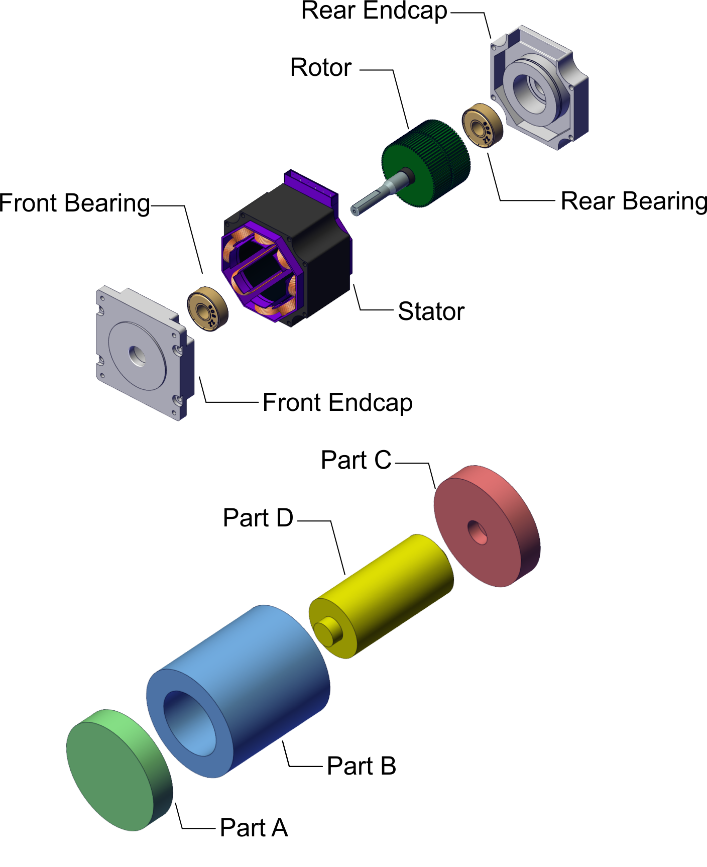

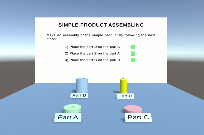
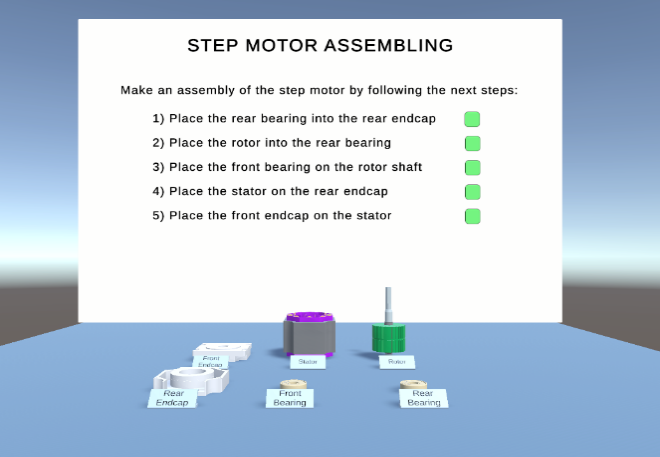
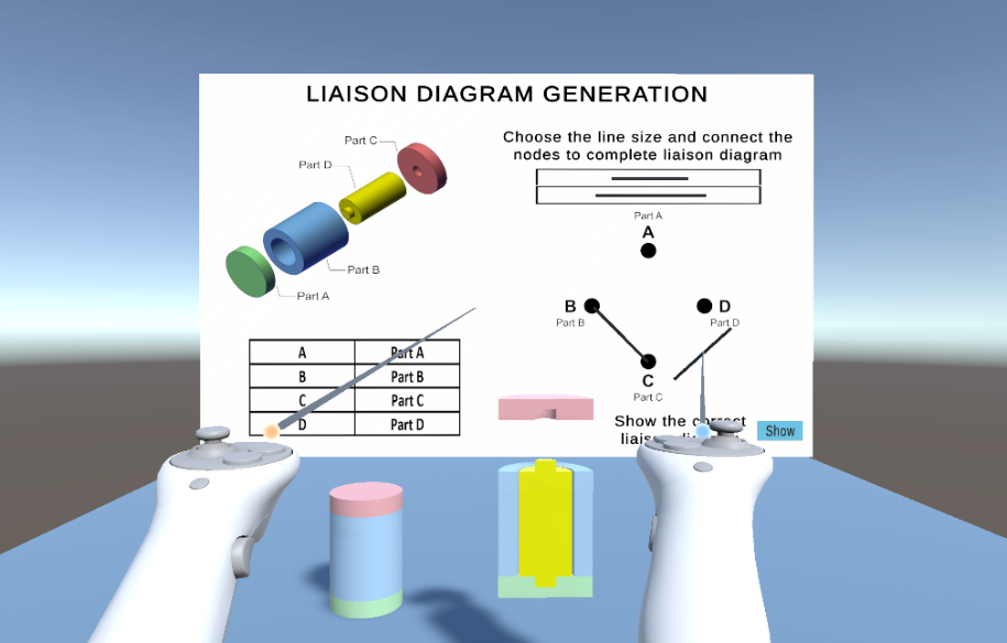
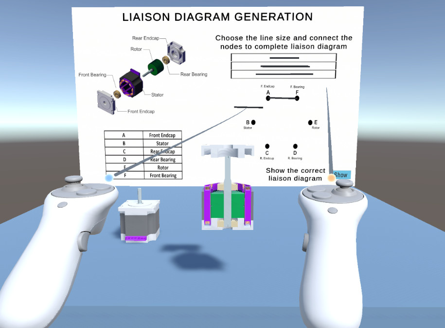
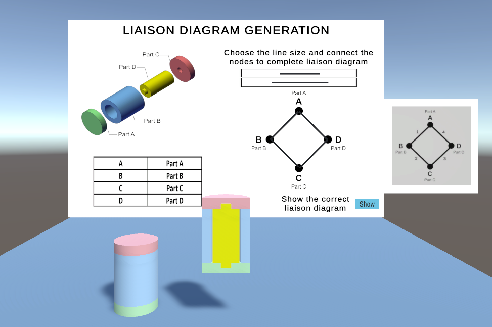
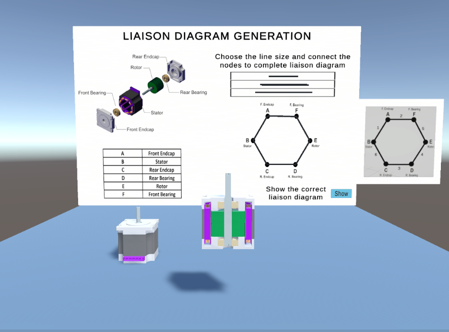
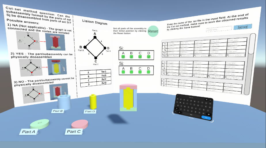
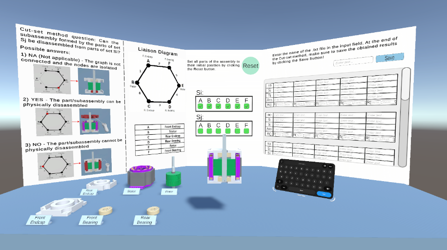
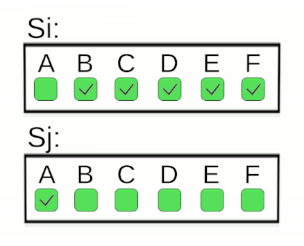
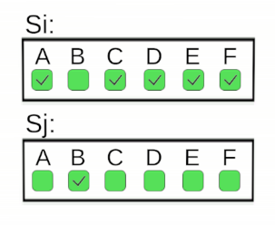
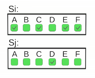
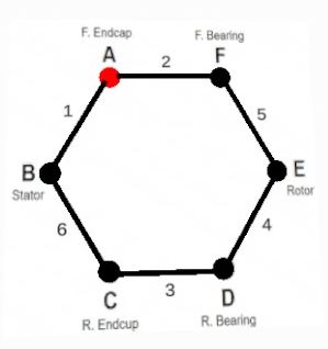
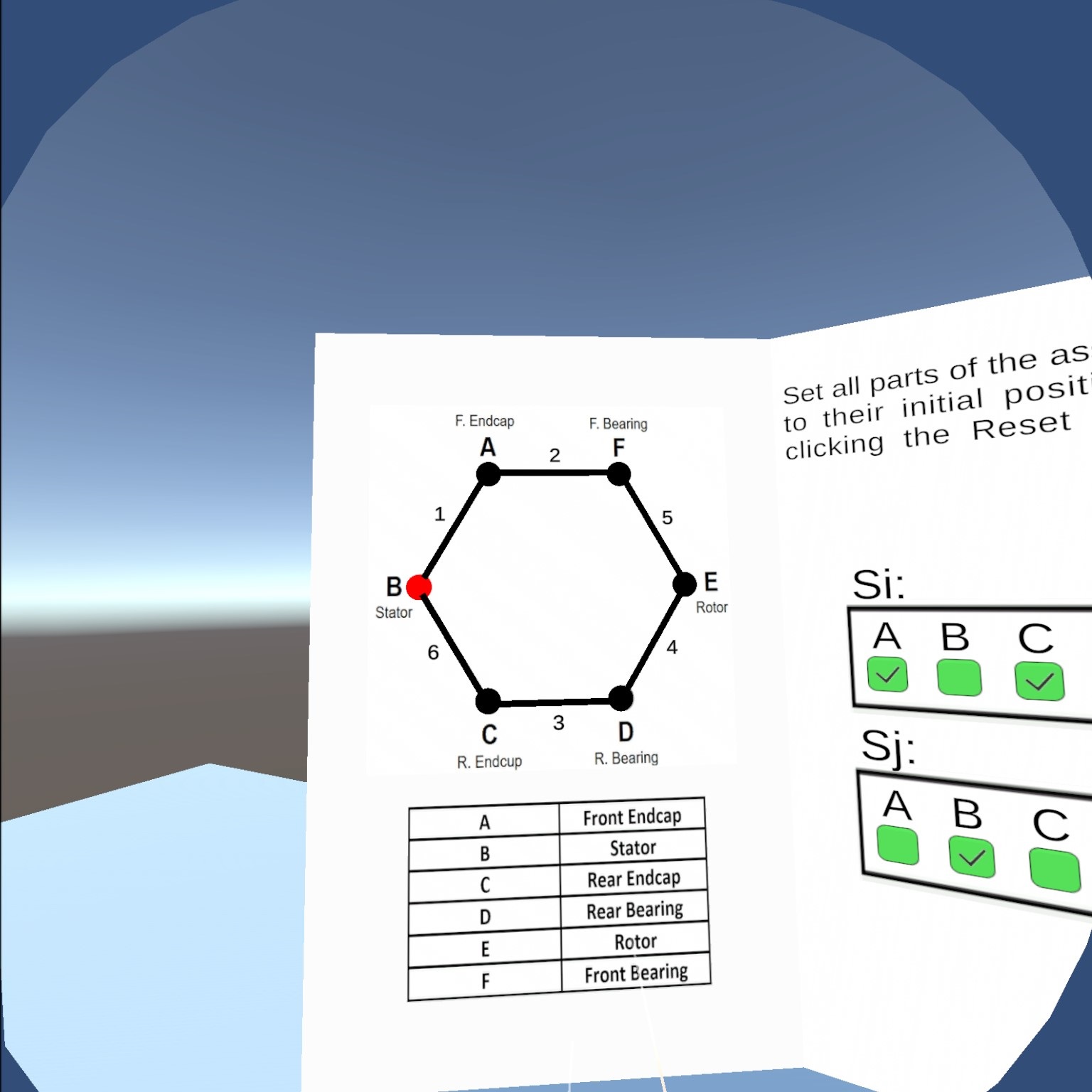
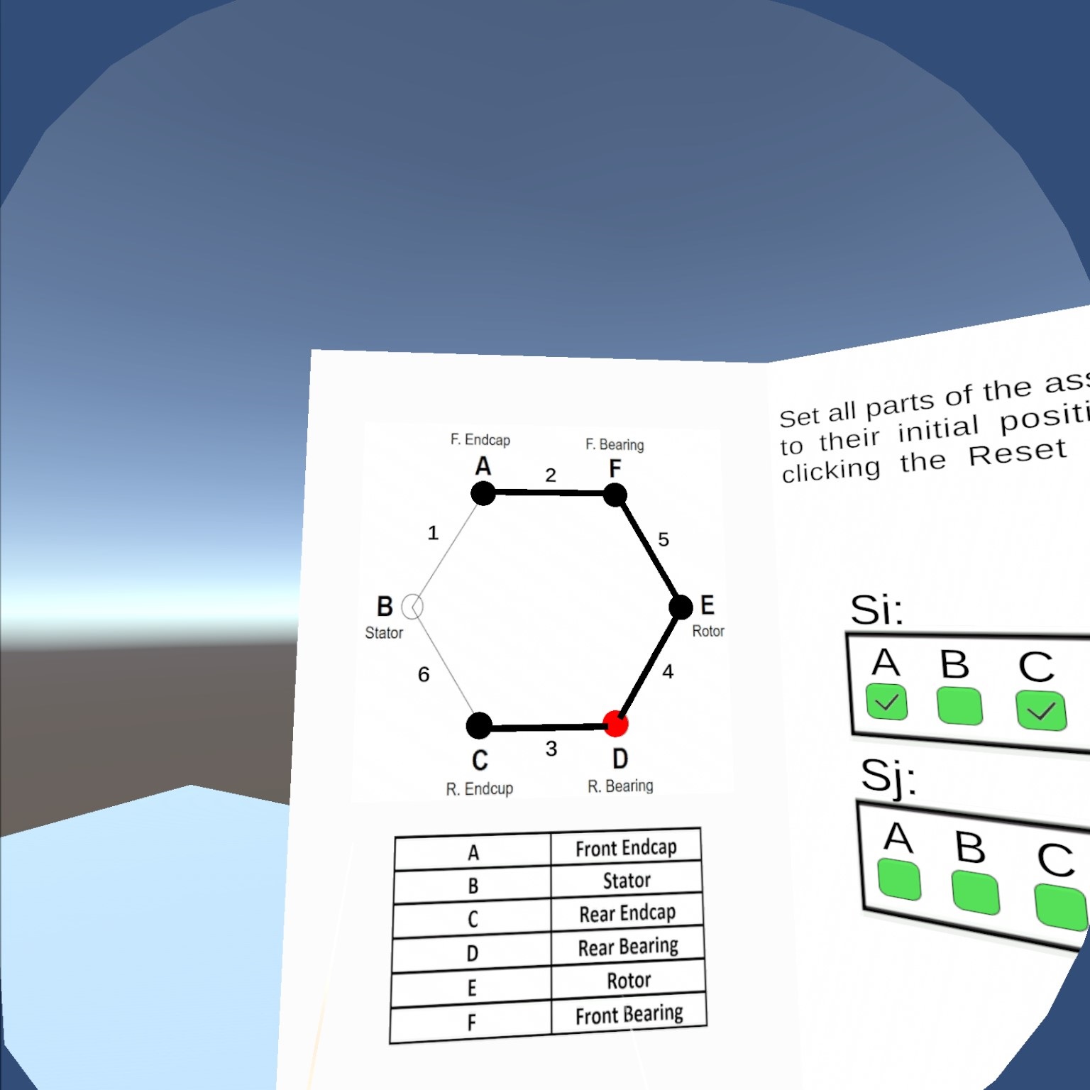
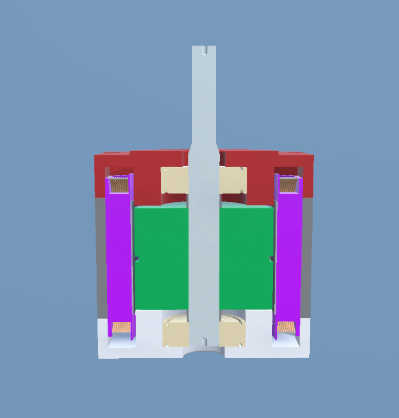

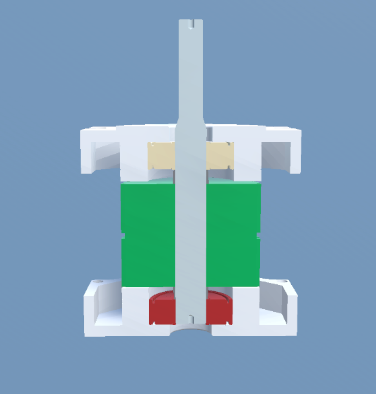
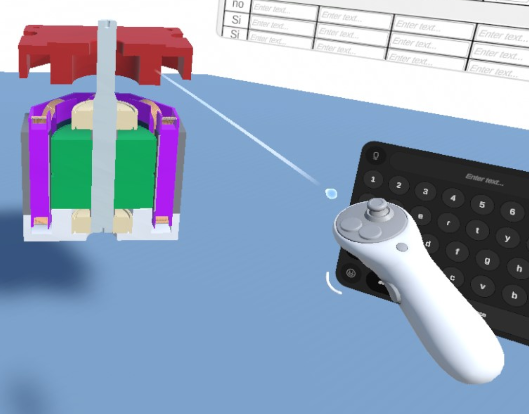
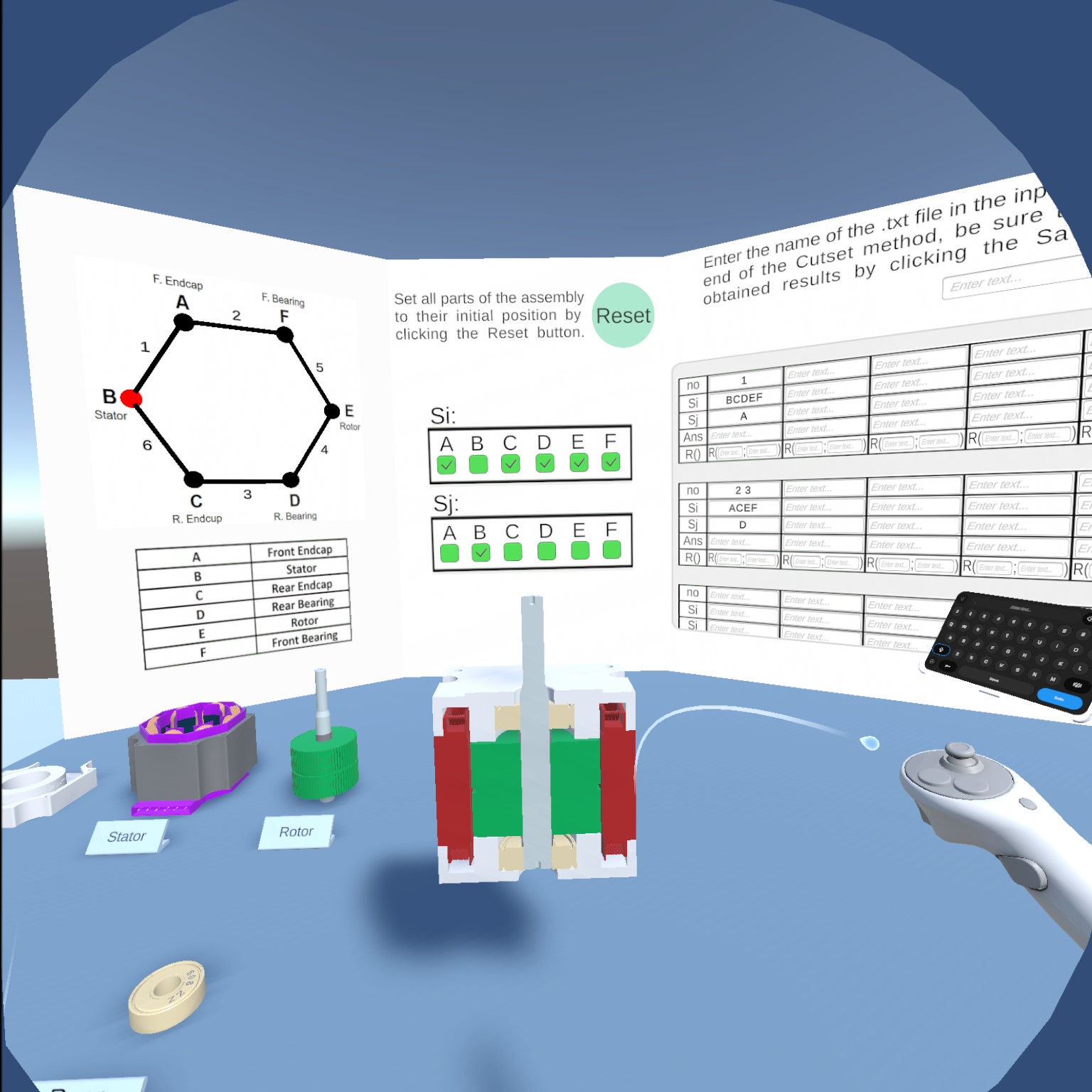
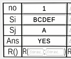
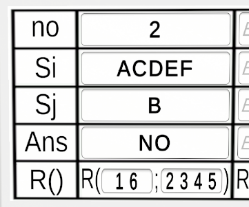
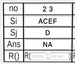
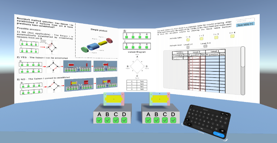
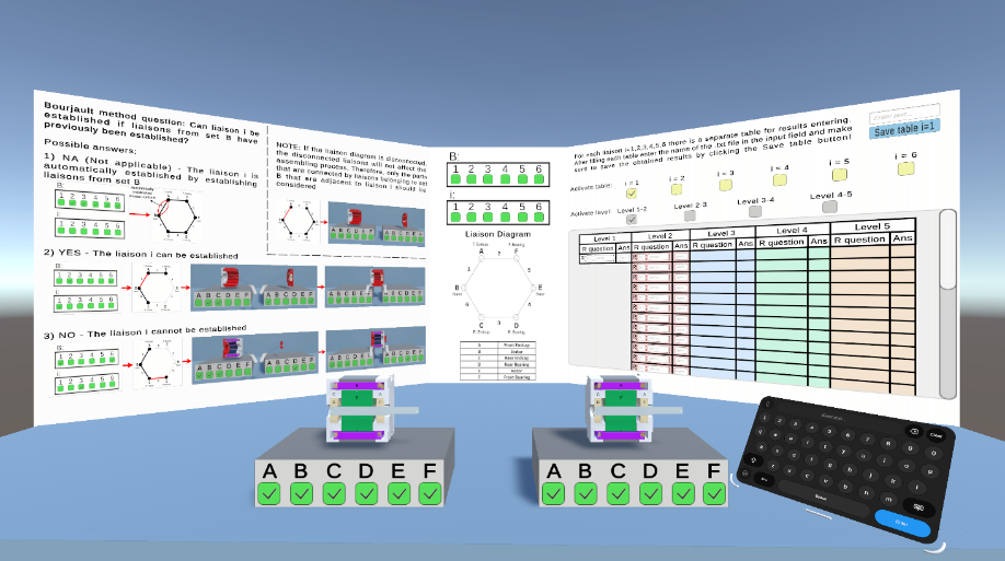
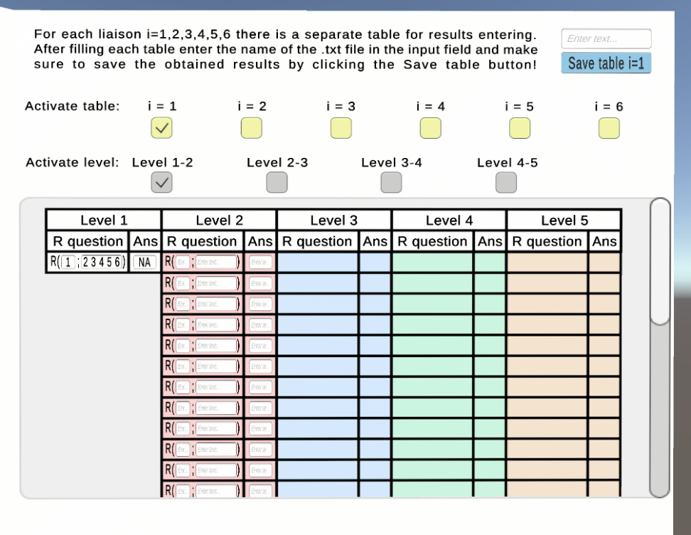
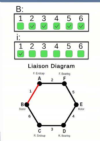
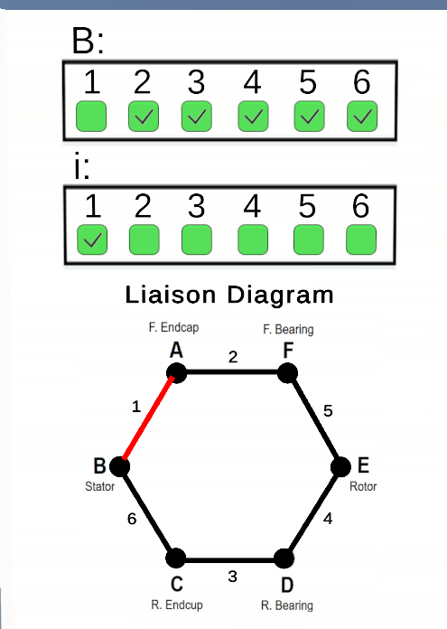
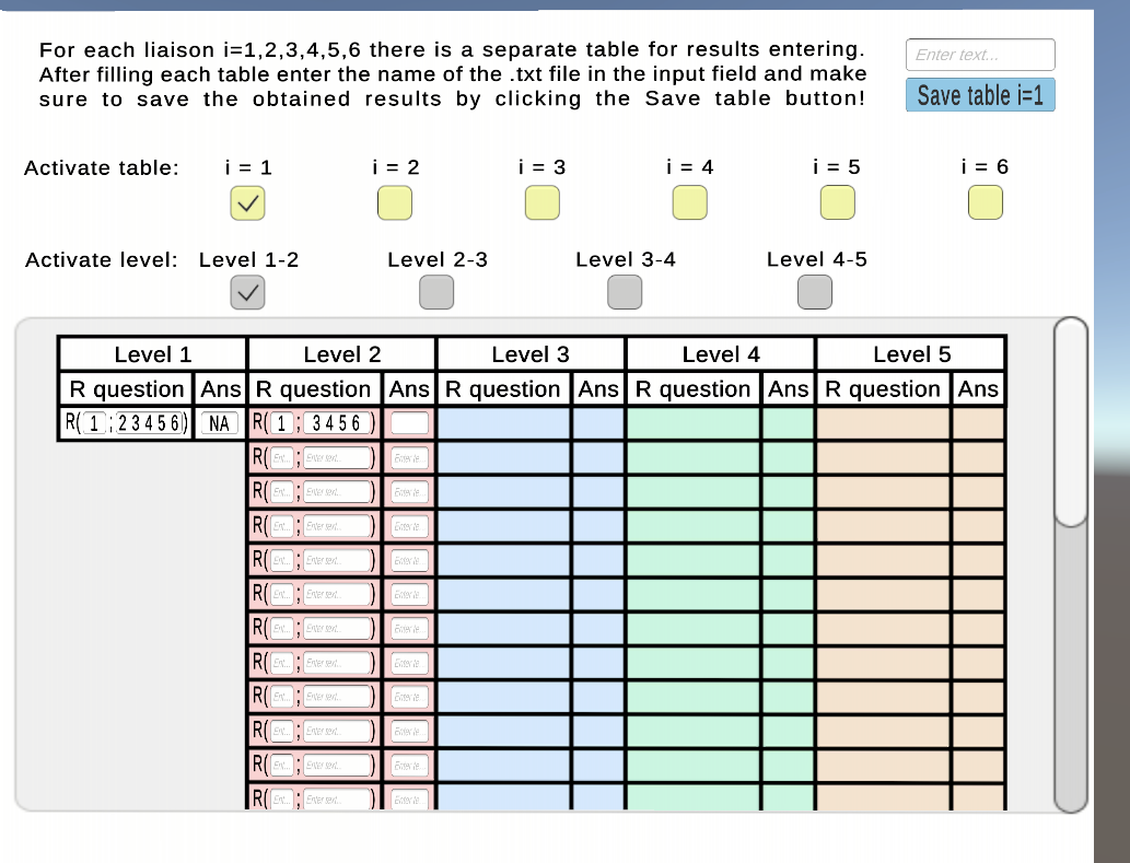
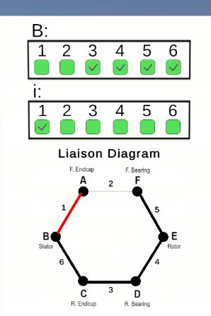
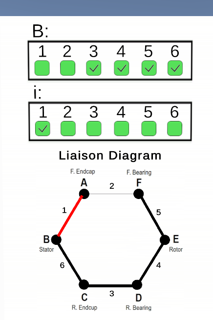
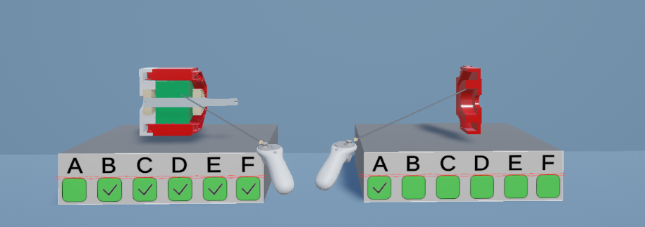
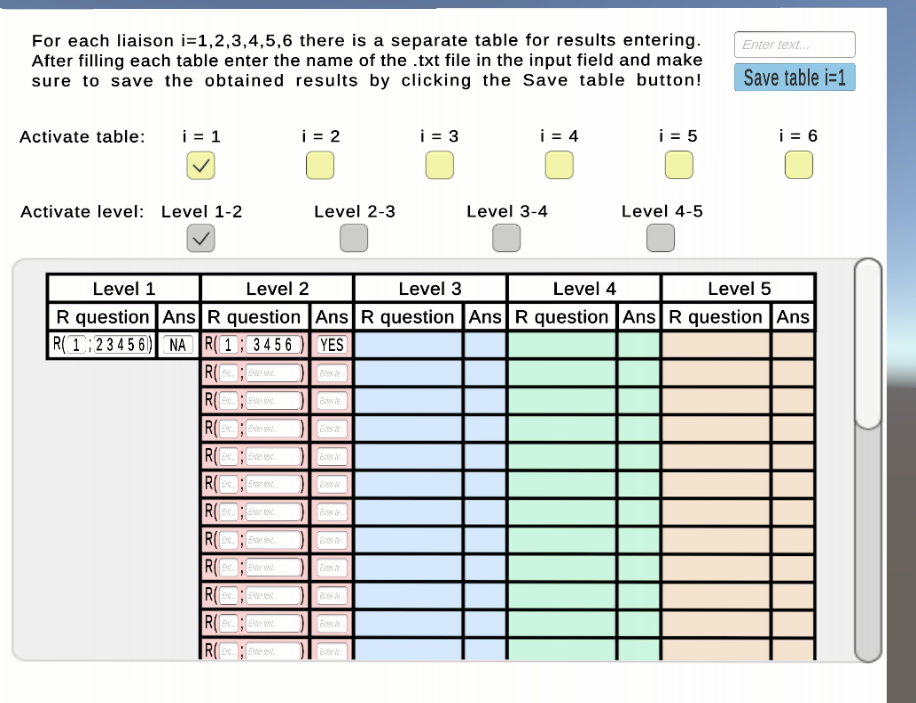





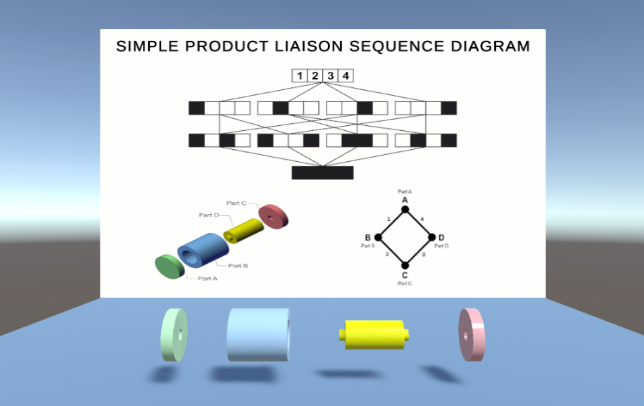
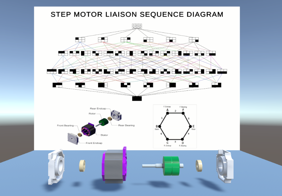
Table 2: Assembly Sequence Design Learning Workflow
4. Technology
Several technologies were utilized for the development of the presented learning workflow. It is primarily based on Unity3D v6000.0.3f1 as a Virtual Reality (VR) development platform. 3D models were created in CAD software (SolidWorks) and imported into Unity 3D using neutral GLTF format, which is lightweight and suitable for real-time rendering. The following automatic functionalities of the VR application were developed and implemented in C#:
-
Control and automatic generation of Liaison Diagrams in scenes for implementation of Cutset and Bourajult methods,
-
Automated turning on/off parts and change of their color to facilitate students’ interaction during assembling/disassembling products,
-
Control of tables for asking and answering precedence questions,
-
Saving and parsing acquired data, etc.
The VR application is [available online].
To prevent the collision between parts and to enable to students close to real-world experience and interaction between parts during assembly in VR, all parts within use cases contain colliders. Since most of the parts in use cases are concave and some of them have complex form, creation of colliders was not a straightforward task. For these purposes open-source library CoACD.unity available at https://github.com/SarahWeiii/CoACD/tree/unity was used. The details regarding this library can be found in [6].

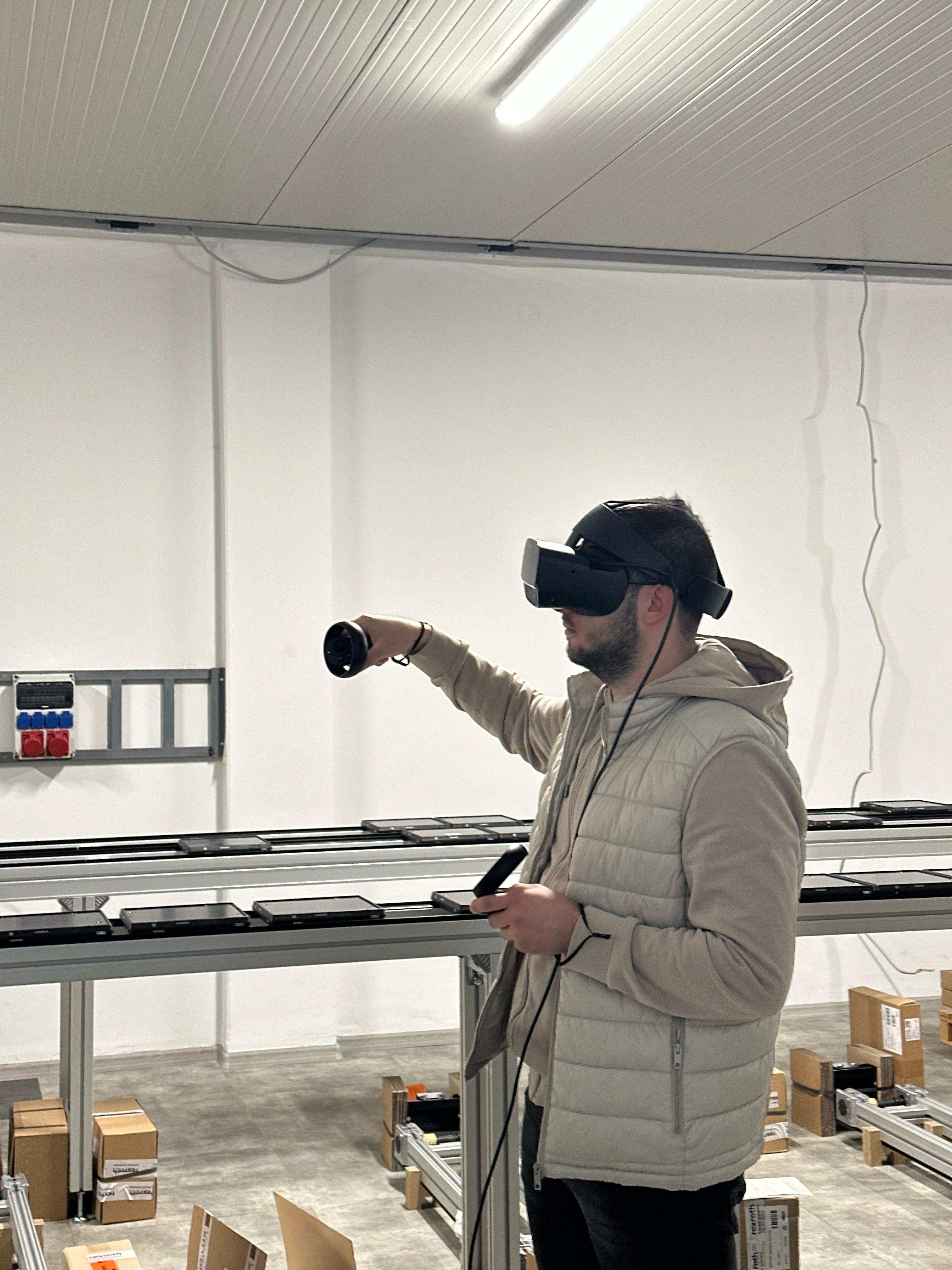
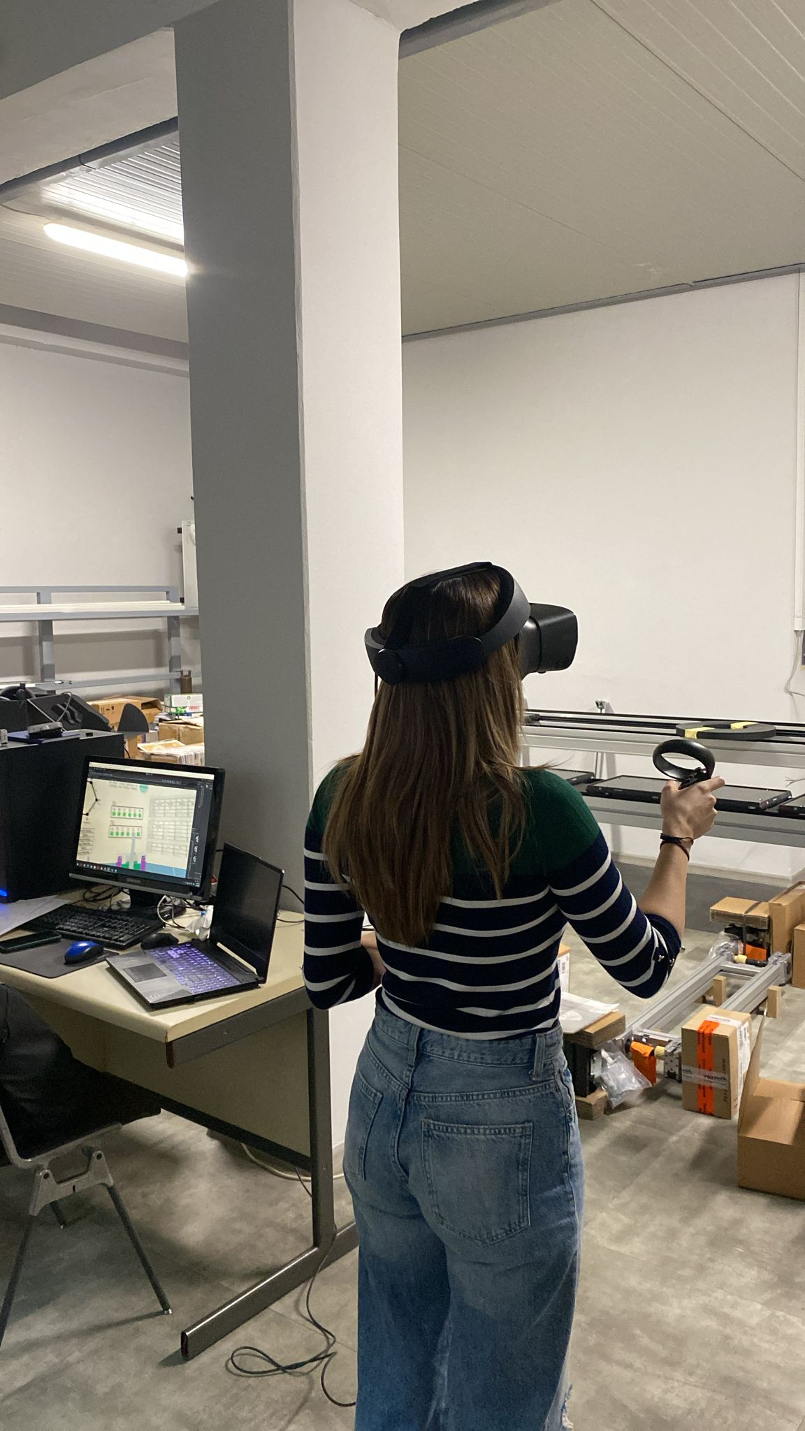
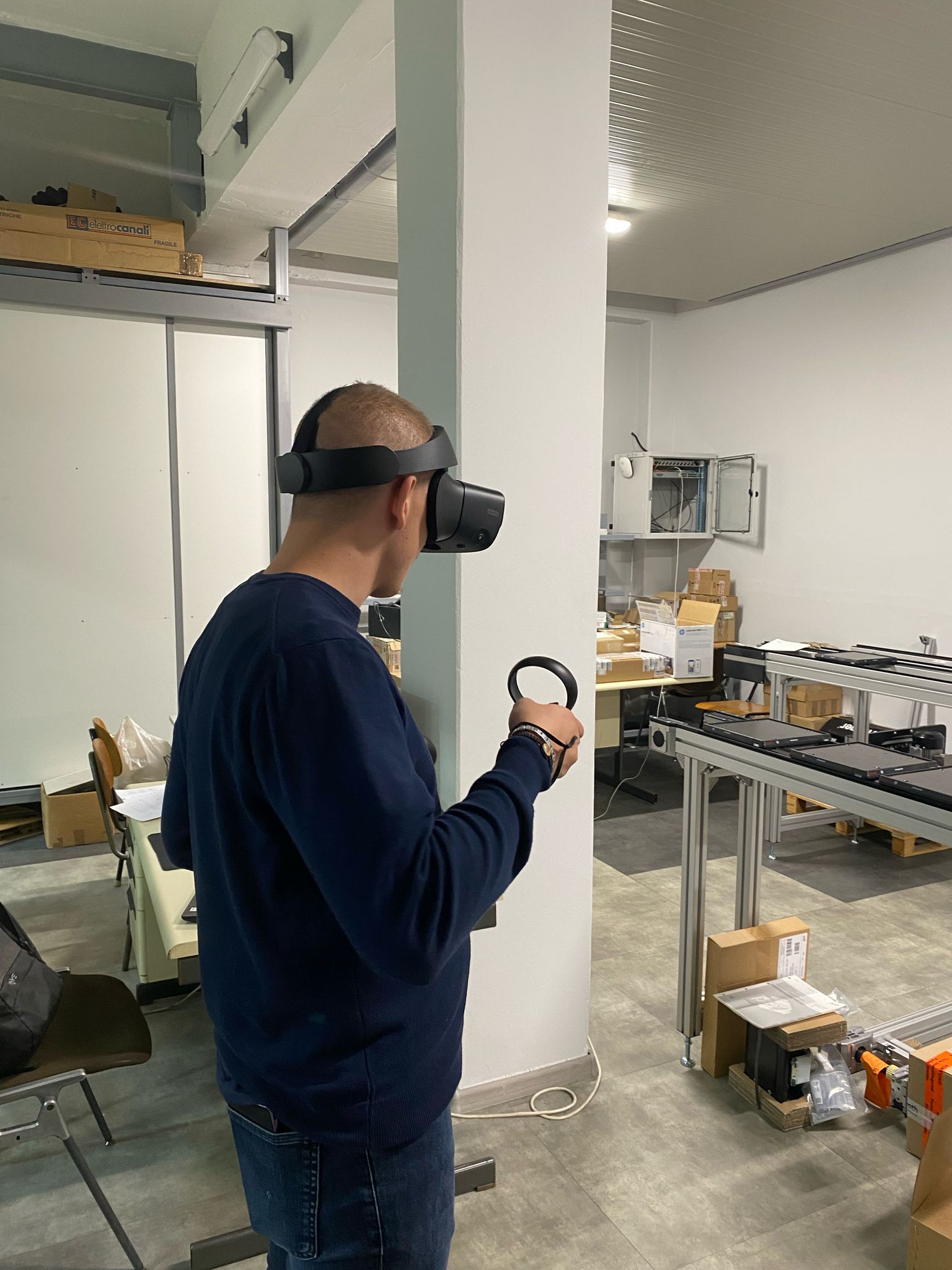
Figure 3: VR device – Oculus Rift S
Oculus Rift S Virtual Reality device including headset with cameras and audio devices, as well as two hand controllers is used providing students with immersive and interactive experience (Figure 3).
5. User Experience
The presented workflow represents a valuable addition to teaching and learning a complex topic of generation of all feasible assembly sequences for given product. Although Cutset and Bourjault methods have precisely specified rules, it is not always easy for students to understand the ways in which these techniques are applied when standard teaching approach is used. This problem is emphasized in situations in which the products used in examples are not available for students hindering their hands-on experience in products’ assembly/disassembly. In certain cases, even when the product is available, it cannot be readily assembled/disassembled for several times to ask and answer precedence questions. For example, in case of step motor there is a tight tolerance between the bearings and rotor on one, and between the bearings and endcaps on the other side, requiring relatively high forces and special tools for their assembly/disassembly. Furthermore, the magnetic field of the rotor makes its assembly/disassembly difficult in real world considering that all other parts are made of ferromagnetic material. In such circumstances hands-on experience can be really annoying for students and counterproductive with respect to learning experience. In presented scenarios, the added value of VR workflow is evident, however its benefits are not limited to overcoming the listed issues.
The workflow provides students with several interactive elements to enhance their understanding of the subject and to contribute to learning outcomes:
1. Interaction with product
Students can engage with the 3D model of product and easily assemble/disassemble it. The existence of colliders within parts makes this experience close to real world, even better to certain extent, since some difficulties experienced in real-world, e.g., related to the forces that should be applied on parts during their assembly, weight of parts, visibility obstacles are not present in VR. This interaction is very important in many steps of the learning workflow including:
-
Detection of mates and joints between product components
-
Generation of Liaison Diagram
-
Asking and answering precedence questions using Cutset and Bourjault methods,
-
Analysis of all feasible sequences and choosing the most suitable among them.
2. Easier engagement and enhanced understanding
Specially generated scenes have several features that make the engagement of students during learning Cutset and Bourjault methods and especially during asking and answering the precedence questions easier. These are:
-
Automatic removal of corresponding liaisons from Liaison Diagram makes it easier to detect subassemblies that are disassembled/assembled during answering precedence questions,
-
The parts to be disassembled in Cutset method, i.e., the parts that create liaison in Bourjault method are marked red making it easier to answer precedence questions,
-
The scenes contain the tables with precedence questions and answers which are structured in a way that make their review by students easier.
All listed features significantly improve students understanding of the methods application.
3. Easier Self-Evaluation
Critical and self-critical thinking represent significant outcomes of engineering education. The important part of the workflow in this context are the elements for self-evaluation of students’ work and in particular for:
-
Liaison Diagram generation,
-
Liaison Sequence Diagram generation.
References
-
D. Whitney, Mechanical Assemblies: Their Design, Manufacture, and Role in Product Development, ser. Advanced manufacturing. Oxford University Press, 2004. [Online]. Available: https://books.google.rs/books?id=4VTjvwEACAAJ
-
A. Bourjault, “Contribution a une approche methodologique de l’assemblage automatise: elaboration automatique des sequences operatoires,” PhD Thesis, Universite de Franche-Comte, France, 1986. [Online]. Available: https://www.sudoc.abes.fr
-
D. F. Baldwin, “Algorithmic methods and software tools for the generation of mechanical assembly sequences,” Thesis (M.S.), Massachusetts Institute of Technology, Dept. of Mechanical Engineering, Boston, USA, 1990. [Online]. Available: https://dspace.mit.edu/handle/1721.1/14006
-
A. Bourjault, “Methodology of assembly automation: A new approach,” in Robotics and Factories of the Future ’87, R. Radharamanan, Ed. Berlin, Heidelberg: Sringer Berlin Heidelberg, 1988, pp. 37–45.
-
Z. Jakovljevic, Assembly Technology, lectures handouts, University of Belgrade – Faculty of Mechanical Engineering, 2024
-
X. Wei, M. Liu, Z. Ling, H. Su, Approximate convex decomposition for 3D meshes with collision-aware concavity and tree search, ACM Transactions on Graphics (TOG), Volume 41, Issue 4, Article No.: 42, Pages 1 – 18, 2022, https://doi.org/10.1145/3528223.3530103